
Mechanical design principles of a mitotic spindle Biology Diagrams In this article, we provide guidelines for identifying specific mitotic stages and for classifying normal and deviant mitotic phenotypes. We hope this will clarify confusion about how certain defects are classified and help investigators avoid misnomers, misclassification, and/or misinterpretation, thus leading to a unified and standardized
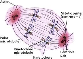
A guide to classifying mitotic stages and mitotic defects in fixed cells Nicolaas C. Baudoin1 & Daniela Cimini1 Received: 14 November 2017/Revised: 7 January 2018 /Accepted: 8 January 2018/Published online: 6 February 2018 mitotic spindle and will constitute the two spindle poles. Fig. 1 Diagrammatic representation of a mitotic cell in

Transient defects of mitotic spindle geometry and chromosome ... Biology Diagrams
impacts mitotic spindle pole integrity. This includes release of MT minus-ends from the centrosome, leading to PCM dispersion and centriole mis-posi-tioning at the spindle poles. Mechanistically, we show that these defects result from abnormal spin-dle MT dynamics due to defective kinetochore-MT attachments. Importantly, restoring mitotic spindle
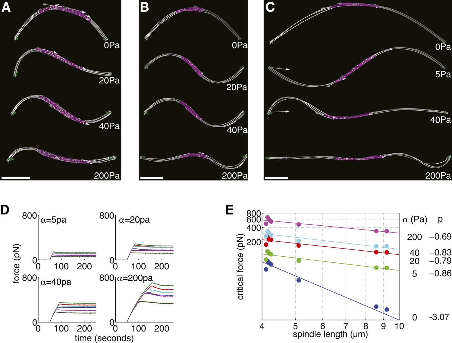
A 2021 study in The Journal of Cell Biology demonstrated that defects in motor protein function can cause mitotic arrest or chromosome lagging, increasing the risk of genomic instability. Pharmacological inhibitors targeting kinesin-5, such as ispinesib, are being explored as potential cancer therapies due to their ability to disrupt spindle The spindle defects caused by OGT and OGA overexpression increased the population of aneuploid cells. 14 In order to determine if OGA knockdown cells produced defective spindles and increased aneuploidy, we stained OGA knockdown and control cells for β-tubulin and DNA and counted the number of cells with aberrant spindles or were multinucleated .

GlcNAcase expression promotes mitotic errors and spindle defects Biology Diagrams
Common mitotic spindle defects. Monopolar spindle induced by kinesin-5 inhibition (10 μm STLC, 90 min) in hTERT RPE-1 cell (a). Prometaphase hTERT RPE-1 cell (same cell as Fig. 1b) with spindle axis oriented perpendicularly to the substrate (b). Images of the two focal planes in which the spindle poles resided are shown in the MT column. In general, lagging chromosomes could be generated by various mechanisms; for example, merotelic attachments (where a single kinetochore attaches to microtubules from opposite spindle poles) would generate lagging chromosomes involving single chromatids, 37 while defects in either sister chromatid resolution or removal of sister chromatid A major contributor to this coordination is the mitotic spindle checkpoint. As detailed in another contribution in this series, defects in mitotic spindle assembly and chromosome alignment activate the spindle checkpoint, which delays cells in M phase. Optimally this delay allows the recovery of the normal spindle and balanced chromosome
